Difference between revisions of "Module Geometry"
From MohidWiki
Davidbrito (talk | contribs) (→Harmonic) |
Davidbrito (talk | contribs) (→Keywords) |
||
| Line 94: | Line 94: | ||
EMPTY_TOP_LAYERS : int [0] !Number of empty layers counting from top | EMPTY_TOP_LAYERS : int [0] !Number of empty layers counting from top | ||
DOMAINDEPTH : real | DOMAINDEPTH : real | ||
| + | LAGRANGIAN : 0/1 [0] !Use lagrangian approach for distorting grometry? | ||
| + | !Layers are displaced with vertical velocity | ||
| + | MINEVOLVELAYERTHICKNESS : real [0.5] !Allowed distortion in percentage of initial thickness | ||
| + | !(if LAGRANGIAN : 1) | ||
| + | DISPLACEMENT_LIMIT : real [1000] !Maximum displacement in meters (if LAGRANGIAN : 1) | ||
<enddomain> | <enddomain> | ||
Revision as of 17:48, 24 May 2013
Contents
Overview
Module Geometry handles the vertical discretization in MOHID. It was designed to divide the water column (in MOHID Water) or the soil compartment (in MOHID Land) in different vertical coordinates: Sigma, Cartesian, Fixed Spacing, Harmonic, etc. A subdivision of the vertical domain into different sub-domains using different vertical coordinate systems is also possible.
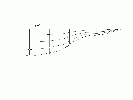
The Module Geometry manages the initialization and the temporal evolution of the grid. The grid must evolve because of surface level evolution, but can also evolve to minimize vertical advective exchanges between cells and thus to minimize numerical diffusion. The vertical exchange between cells will result into a grid that is locally parallel to the velocity.
The Cartesian coordinates are adequate when the flow is horizontal. This is the case when the baroclinic pressure is important as happens in systems with very low free surface gradient or in deep systems where even small density gradients can result into important baroclinic pressure gradients when the density gradient is integrated along depth.
Sigma coordinates are convenient when the pressure gradient is barotropic. In this case the pressure force is the same over the whole water column and vertical velocity gradients are due mostly to bottom friction. In these cases the velocity tends to be parallel to the sigma lines.
In reality the flow is never horizontal or along the sigma lines, because the pressure is never purely barotropic or baroclinic, but also due to inertia forces. As a consequence the best grid is that which is able to react as a function of the local vertical velocity. This is the “lagrangian coordinate”. The Lagrangian coordinate must thus be able to manage grid initiated as Cartesian or as Sigma, but must also be able to manage situations when the level changes dramatically in time, as is the case of artificial reservoirs.
The concept of vertical domain was created to combine different coordinates, being common to use a Cartesian domain in the lower part of deep systems and a Sigma domain on the top to simulate the continental shelf or very coastal zones.
The Module Geometry was developed into steps following concepts’ evolution. Initially the aim was only to permit Cartesian or Sigma coordinates (i.e. easy the use of the finite-volume concept), then it evolved to allow small vertical deformation of the grid along the lagrangian concept described above and finally it evolved to allow large reservoir free surface changes (the so called Harmonic grid). In this last case layer could shrink between a minimum and a maximum thickness. This coordinate was used on a top domain to include the region within the range of free surface level change.
General options
- Minimum depth
Lagrangian Process
The Lagrangian process moves the layers faces with the vertical flow velocity. It can be called to change geometry in Sigma and Cartesian coordinates. The layer displacement is limited by a minimum and a maximum cell thickness (shrinking or expansion). These values are defined by the user as a percentage of the initial cell thickness (i.e. of the values provided in the input file to define the geometry).
Vertical coordinate system
Sigma
Cartesian
The Cartesian coordinate can be used with or without shaved cells. Cartesian builds layers from Hydrographic Zero or Domain Depth to bottom layer with fixed depth of each layer. In the end of the process, if cartesian is the upper domain, the top layer face is equalized to surface level.
Fixspacing
The Fixed Spacing coordinate allows the user to study flows close to the bottom.
Harmonic
Harmonic Coordinate is going to be discontinued
The Harmonic coordinate works like the Cartesian coordinate, just that the horizontal faces close to the surface expand and collapse depending on the variation of the surface elevation. This coordinate was implemented in the geometry module to simulate reservoirs.
Fixsediment
SigmaTop
Cartesiantop
Cartesiantop is equal to cartesian but builds layers from top to bottom. This type of coodinates are used for Mohid Land. The top is the topography and the bottom is the non-porousmedia (rock). This means that in lower depth soils there will be less layers than in higher depth soils.
Distances
Public routines
- ModuleHorizontalGrid
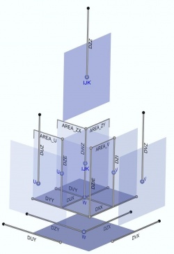
- GetHorizontalGrid(HorizontalGridID, XX_IE, YY_IE, XX_Z, YY_Z,XX_U, YY_U, XX_V, YY_V, XX_Cross, YY_Cross, DXX, DYY, DZX, DZY, DUX, DUY, DVX, DVY, XX, YY, XX2D_Z, YY2D_Z, STAT)
- ModuleGeometry
- GetGeometryDistances(GeometryID, SZZ, DZZ, DWZ, DUZ, DVZ, DZI, DZE,ZCellCenter, ActualTime, STAT)
Areas
Volumes
Bathymetry consistency diagnostic
Once the vertical discretization is imposed and the bathymetry is chosen, the bottom layer can yield stability problems when using shaved cells. You can have very thin bottom cell next to a very wide bottom cell. To diagnose the existence of such problematic cells, a geometry diagnostic tool was developed.
Input data file
Keywords
WINDOW                        : 0/1               [0]         !1 Avoid check bottom depth and geometry consistency

IMPERMEABILITY                : 0/1               -           !Consider impermeable cell faces
IMPER_COEF_U                  : real             [1]          !
IMPER_COEFX_U                 : real             [0]          !
IMPER_COEF_V                  : real             [1]          !
IMPER_COEFX_V                 : real             [0]          !

<begindomain>
  ID                          : int               -           !Domain ID
  TYPE                        : char              -           !Type of vertical coordinate of the domain
                                                              !Multiple options: FIXSPACING, SIGMA,
                                                              !LAGRANGIAN, CARTESIAN, HARMONIC, FIXSEDIMENT, CARTESIANTOP.
  LAYERS                      : int               -           !Number of layers
  EQUIDISTANT                 : real             [0]          !Equidistant layers spacing in meters
  LAYERTHICKNESS              : real vector       -           !If not equidistant specifies layers thickness
                                                              !starting from bottom layer (e.g. 50. 20. 10. 5.)
  TOLERANCEDEPTH              : real            [0.05]        !Just for SIGMA,ISOPYCNIC, LAGRANGIAN coordinates
  TOTALTHICKNESS              : real              -           !Total domain thickness
                                                              !(Just for FIXSPACING, FIXSEDIMENT, SOIL_TOPLAYER)
  EMPTY_TOP_LAYERS            : int              [0]          !Number of empty layers counting from top
  DOMAINDEPTH                 : real
  LAGRANGIAN                  : 0/1              [0]          !Use lagrangian approach for distorting grometry?
                                                              !Layers are displaced with vertical velocity
  MINEVOLVELAYERTHICKNESS     : real            [0.5]         !Allowed distortion in percentage of initial thickness
                                                              !(if LAGRANGIAN : 1)
  DISPLACEMENT_LIMIT          : real           [1000]         !Maximum displacement in meters (if LAGRANGIAN : 1)
<enddomain>


