Difference between revisions of "How to create a MOHID Land Project Step-by-Step"
From MohidWiki
Davidbrito (talk | contribs) (→PorousMedia data file) |
Davidbrito (talk | contribs) |
||
| (45 intermediate revisions by 2 users not shown) | |||
| Line 1: | Line 1: | ||
| + | =MOHID Old Interface - MOHID GUI, MOHID GIS and MOHID Time Serie Editor= | ||
| + | |||
==Creating a new GUI Project== | ==Creating a new GUI Project== | ||
| Line 20: | Line 22: | ||
===Create a topography grid data=== | ===Create a topography grid data=== | ||
To create a topography file you will need: | To create a topography file you will need: | ||
| − | #Topography data. See [[ConvertToXYZ]] | + | #Topography data. See [[ConvertToXYZ#NASA_Topography|Convert data from NASA Topography]]. |
#grid. See [[Grid]] and [[GenerateGrid]] pages. | #grid. See [[Grid]] and [[GenerateGrid]] pages. | ||
| − | #Create the grid data with the topography | + | #Create the grid data with the topography being interpolated to the grid. See [[MOHID_GIS#Create_Digital_Terrain|MOHID GIS Terrain Creator]] or [[Digital_Terrain_Creator|Digital Terrain Creator Tool]] or can use one already created as reference. |
| + | #Remove depressions from the topography using [[MOHID_GIS#Remove_Depression|MOHID GIS Remove Depressions]]. | ||
===Define Topography in GUI=== | ===Define Topography in GUI=== | ||
| Line 71: | Line 74: | ||
==Geometry data file== | ==Geometry data file== | ||
| − | Here you can define your vetical coordinate. Use '''CARTESIANTOP''' as default. | + | Here you can define your vetical coordinate. Use [[Module_Geometry#Cartesiantop|'''CARTESIANTOP''']] as default. |
Define number of layers and their thickness. | Define number of layers and their thickness. | ||
| Line 110: | Line 113: | ||
DRAINAGE_NET : 1 | DRAINAGE_NET : 1 | ||
| − | If evapotranspiration is to be used potential evapotranspiration can be: i) computed from Penman-Montheith method or ii) defined from file or constant value (as for | + | If evapotranspiration is to be used potential evapotranspiration can be: i) computed from Penman-Montheith method or ii) defined from file or constant value (as for [[Module_FillMatrix|Module FillMatrix]] standards). The example below shows the case where potential evapotranspirtation will be computed from Penman-Motheith method because no constant value or file is given. |
<beginproperty> | <beginproperty> | ||
NAME : reference evapotranspiration | NAME : reference evapotranspiration | ||
| Line 136: | Line 139: | ||
==Drainage_Network data file== | ==Drainage_Network data file== | ||
| − | *A drainage network file containing nodes and cross sections is needed [[ | + | *A drainage network file containing nodes and cross sections is needed. See [[Module_DrainageNetwork#Creatig_a_drainage_network_file|How to create a drainage network]]. |
| + | |||
*Please follow [[Module DrainageNetwork| Module Drainage Network]] for more details on processes and data file keywords. | *Please follow [[Module DrainageNetwork| Module Drainage Network]] for more details on processes and data file keywords. | ||
==Run_Off data file== | ==Run_Off data file== | ||
| − | * | + | *Manning coefficients must be provided. See [[Module_Runoff#How_To_Generate_Manning_Coefficients|How to generate Manning coefficients]]. |
*Please follow [[Module_Runoff| Module Runoff]] for more details on processes and data file keywords. | *Please follow [[Module_Runoff| Module Runoff]] for more details on processes and data file keywords. | ||
==PorousMedia data file== | ==PorousMedia data file== | ||
| − | + | This data should be gathered for porous media: | |
| − | + | * Soil Map and soils hydraulic caracteristics | |
| − | + | * Soil Bottom Altitude | |
| − | + | * Water Table Altitude | |
| − | + | * Surface Impermeability | |
| − | + | See [[Module_PorousMedia#How_to_Generate_Info_needed_in_Porous_Media|How to Generate Porous Media Data]] | |
| − | |||
| − | |||
| − | |||
| − | |||
| − | |||
| − | |||
| − | |||
| − | |||
*Please follow [[Module_PorousMedia| Module Porous Media]] for more details on processes and data file keywords. | *Please follow [[Module_PorousMedia| Module Porous Media]] for more details on processes and data file keywords. | ||
| Line 165: | Line 161: | ||
==Vegetation data file== | ==Vegetation data file== | ||
| − | *A vegetation grid must be provided. | + | *A vegetation grid with ID's from each vegetation type must be provided. See [[Module_Vegetation#How_to_generate_the_vegetation_grid|How to generate the vegetation grid]]. |
*Please follow [[Module_Vegetation| Module Vegetation]] for more details on processes and data file keywords. | *Please follow [[Module_Vegetation| Module Vegetation]] for more details on processes and data file keywords. | ||
| Line 202: | Line 198: | ||
Check also in [[How_to_create_MOHID_timeseries_outputs | How to define time series outputs in MOHID]] for other details. | Check also in [[How_to_create_MOHID_timeseries_outputs | How to define time series outputs in MOHID]] for other details. | ||
| + | |||
| + | |||
| + | =MOHID New Interface - MOHID Studio= | ||
| + | Check Mohid Studio Manual inside Studio | ||
| + | |||
| + | =Troubleshooting= | ||
| + | Frequent Issues | ||
| + | #If Porous Media taking too long to run: Check that you are using last executable. Geometry changes improved model perfomance. | ||
| + | #If Porous Media or Drainage Network is taking too long to run and if your project is in Geographic Coordinates, check GEO_CONVERSATION_FACTOR in drainage network data file: it is the metric to degrees relation at your latitude. | ||
| + | [[Category: MOHID_Land]] | ||
Latest revision as of 11:11, 9 September 2011
Contents
- 1 MOHID Old Interface - MOHID GUI, MOHID GIS and MOHID Time Serie Editor
- 1.1 Creating a new GUI Project
- 1.2 Topography
- 1.3 Model data file
- 1.4 Atmosphere data file
- 1.5 Geometry data file
- 1.6 Basin_Geometry data file
- 1.7 Basin data file
- 1.8 Drainage_Network data file
- 1.9 Run_Off data file
- 1.10 PorousMedia data file
- 1.11 PorousMediaProperties data file
- 1.12 Vegetation data file
- 1.13 Output
- 2 MOHID New Interface - MOHID Studio
- 3 Troubleshooting
MOHID Old Interface - MOHID GUI, MOHID GIS and MOHID Time Serie Editor
Creating a new GUI Project
- Run MOHID GUI (usually you can find it in the StartMenu->Programs->MOHID)
- Choose Menu Project and then New
- Name the project, the filename and give the project folder (usually in ../Aplica/MohidLand/[ApplicationName]/
- Insert a new simulation right clicking the project icon in the left, as shown in the Figure 1. The simulation aggregates model runs with the same topography.
- Define the simulation name (that you can easilly identify) and define MOHID Land radio button defined in Figure 2
- Insert a new run right clicking the simulation icon in the left, as shown in the Figure 3. The run is each model simulation.
- Define the run name (that you can easilly identify) and couple modules that you need and are not checked (e.g. vegetation) as seen in Figure 4.
- How to create a new simulation and runs
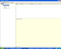
Figure 1: How to insert new simulation
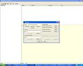
Figure 2: How to insert new simulation, settings
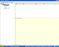
Figure 3: How to insert a new run
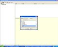
Figure 4: How to insert a new run, coupled modules


Topography
Create a topography grid data
To create a topography file you will need:
- Topography data. See Convert data from NASA Topography.
- grid. See Grid and GenerateGrid pages.
- Create the grid data with the topography being interpolated to the grid. See MOHID GIS Terrain Creator or Digital Terrain Creator Tool or can use one already created as reference.
- Remove depressions from the topography using MOHID GIS Remove Depressions.
Define Topography in GUI
The topography is defined for the simulation and is the same for all runs. As so, is defined in the simulation window.
- Click on the simulation name once to select it.
- Right click on the simulation name to show the menu
- Select <Properties>
- In the property window in grid data, browse for your topography grid data.
Model data file
Here you can:
- edit simulation start and simulation end:
START                         : 2002 10 1 0 0 0
END                           : 2004 10 1 0 0 0
- edit model timestep:
DT : 100.
- use variable timestep to account for rain periods with higher gradients:
VARIABLEDT : 1
- define maximum time step, if using variable timestep:
MAXDT : 3600.0
Atmosphere data file
Here you give atmosphere properties to force the model using the block:
<beginproperty>
NAME                    : precipitation
UNITS                   : mm
DESCRIPTION             : precipitation
...
<endproperty>
Properties may be entered as constant values, time series or HDF. Check Module Atmosphere for property info and Module FillMatrix for property keywords (e.g. evolution in time and space).
If you want to:
- Create property timeseries files, follow Time Series
- Create property HDF5 files from meteorological data (e.g. MM5), follow ConvertToHDF5
- Create property HDF5 files from station time series data (precipitation, humidity, temperature, etc.), follow FillMatrix
Remarks
If you want to account for the exact amount of precipitation using a time serie or hdf file as input, then in property precipitation block choose:
NO_INTERPOLATION : 1
In this way the precipitation in any time step is the one from the next available instant and so on, not being interpolated between timeserie or hdf instants.
- Please follow Module Atmosphere for more details on processes and data file keywords.
Geometry data file
Here you can define your vetical coordinate. Use CARTESIANTOP as default. Define number of layers and their thickness.
<begindomain>
ID                      : 1
TYPE                    : CARTESIANTOP
LAYERS                  : 13
LAYERTHICKNESS          : 7 6 5 4 3 2 2 1 0.5 0.3 0.2 0.1 0.1
MIN_BOTTOM_THICKNESS    : 0.1
<enddomain>
Also define minimum layer depth:
MINIMUMDEPTH : 0.1
Basin_Geometry data file
Here you define the delineation of your watershed inside the model grid.
DELINEATE_BASIN               : 1
OUTLET_I                      : 24
OUTLET_J                      : 79
TRESHOLD_AREA                 : 100000
This keywords allow to delineate the basin, define where will be the outlet (i,j) and define minimum area to start considering a river node.
If the simulation is not a watershed (e.g. 2D vertical or other schematic tests) then delineation is not needed and the only thing to do is define boundary points (flat solution keyword on):
DELINEATE_BASIN               : 0
FLAT_SOLUTION                 : 1
TRESHOLD_AREA                 : 100000
In the latter case, also define a treshold area bigger than your area if you do not want rivers.
Basin data file
Basin model manages all other models information and here are defined which models will be used (as an example):
ATMOSPHERE             : 1
EVAPOTRANSPIRATION     : 1
VEGETATION             : 1
POROUS_MEDIA           : 1
POROUS_MEDIA_PROPERTIES: 0
RUN_OFF                : 1
DRAINAGE_NET           : 1
If evapotranspiration is to be used potential evapotranspiration can be: i) computed from Penman-Montheith method or ii) defined from file or constant value (as for Module FillMatrix standards). The example below shows the case where potential evapotranspirtation will be computed from Penman-Motheith method because no constant value or file is given.
<beginproperty>
NAME                    : reference evapotranspiration
UNITS                   : m/s
DESCRIPTION             : fao evapotranspiration
DEFAULTVALUE            : 0.0
REMAIN_CONSTANT         : 0
<endproperty>
Remarks
If the user chooses not to include vegetation with the keyword:
VEGETATION : 0
then transpiration is not computed. However, the user may want to still evaporate water from soil surface. To do so, evapotranspiration must be enabled:
EVAPOTRANSPIRATION : 1
and reference evapotranspiration property must be defined. Then, in this case, the reference evapotranspiration will be in the form of potential evaporation.
In the other end, if the user chooses to include vegetation with the keyword:
VEGETATION : 1
The user may want to compute: i) a global potential evapotranspiration or ii) separate potential transpiration (in plants along the root depth) and potential evaporation (on soil surface) based on leaf area index. This option is defined with the keyword:
EVAPOTRANSPIRATION_METHOD: 1/2 (1-Global Evapotranspiration; 2-Transpiration and Evaporation)
The default value is 1 (if the keyword is not entered).
Drainage_Network data file
- A drainage network file containing nodes and cross sections is needed. See How to create a drainage network.
- Please follow Module Drainage Network for more details on processes and data file keywords.
Run_Off data file
- Manning coefficients must be provided. See How to generate Manning coefficients.
- Please follow Module Runoff for more details on processes and data file keywords.
PorousMedia data file
This data should be gathered for porous media:
- Soil Map and soils hydraulic caracteristics
- Soil Bottom Altitude
- Water Table Altitude
- Surface Impermeability
See How to Generate Porous Media Data
- Please follow Module Porous Media for more details on processes and data file keywords.
PorousMediaProperties data file
- Please follow Module Porous Media Properties for more details on processes and data file keywords.
Vegetation data file
- A vegetation grid with ID's from each vegetation type must be provided. See How to generate the vegetation grid.
- Please follow Module Vegetation for more details on processes and data file keywords.
Output
Define HDF output
Define the output time for the HDF files in each module data file:
OUTPUT_TIME : 0 86400
The output will be done in modules basin, runoff, drainage network, porous media for standard properties; for modules vegetation and atmosphere the output will be done for properties with the following keyword connected:
OUTPUT_HDF : 1
Define time series output
To create time serie outputs create a .dat file and one block <BeginTimeSerie> <EndTimeSerie> for each location with the name and grid index to output:
DT_OUTPUT_TIME                :  3600
MAX_BUFFER_SIZE               :  10000

<BeginTimeSerie>
NAME                          : Outlet
LOCALIZATION_I                :  24
LOCALIZATION_J                :  79
LOCALIZATION_K                :  13
<EndTimeSerie>

<BeginTimeSerie>
NAME                          : Ponte Zambujal
LOCALIZATION_I                :  72
LOCALIZATION_J                :  65
LOCALIZATION_K                :  13
<EndTimeSerie>
Then in each data file that you want time serie output (basin, runoff, drainage network, porous media, vegetation, atmosphere), point to the created file with the keyword:
TIME_SERIE_LOCATION : ..\GeneralData\TimeSeries\GenericTimeSeries.dat
The output will be done in modules basin, runoff, drainage network, porous media for standard properties; for modules vegetation and atmosphere the output will be done for properties with the following keyword connected:
TIME_SERIE : 1
Check also in How to define time series outputs in MOHID for other details.
MOHID New Interface - MOHID Studio
Check Mohid Studio Manual inside Studio
Troubleshooting
Frequent Issues
- If Porous Media taking too long to run: Check that you are using last executable. Geometry changes improved model perfomance.
- If Porous Media or Drainage Network is taking too long to run and if your project is in Geographic Coordinates, check GEO_CONVERSATION_FACTOR in drainage network data file: it is the metric to degrees relation at your latitude.