Module PorousMedia
From MohidWiki
Contents
Overview
Main Processes
Water flow
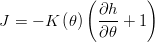
The water movement in soil will be dependent on the pressure gradients existing in the soil profile and also according to gravity. The equation that describes this motion is the Buckingham Darcy equation (Jury et al,1991) where J is the water velocity, h is the pressure head, θ is the water content and K is the hydraulic conductivity.
Water retention
The shape of water retention curves can be characterized by several models, one of them known as the van Genuchten model:
![\theta(h) = \theta_r + \frac{\theta_s - \theta_r}{\left[ 1+(\alpha |h|)^n \right]^{1-1/n}}](/images/math/b/c/6/bc65430258eab7b04691c802a4aaa760.png)
where
 is the water retention curve [L3L−3];
 is suction pressure ([L−1] or cm of water);
 saturated water content [L3L−3];
 residual water content [L3L−3];
 is related to the inverse of the air entry suction,
  ([L−1], or cm−1); and,
 is a measure of the pore-size distribution,
  (dimensionless).
Evapotranspiration
Some water may disappear from the soil because of the evaporation and transpiration processes, which become a sink in soil water profile. These two processes, currently named Evapotranspiration may be modeled using the Penmann Monteith equation.
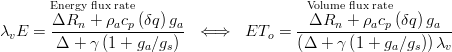
- λv = Latent heat of vaporization. Energy required per unit mass of water vaporized. (J/g)
- Lv = Volumetric latent heat of vaporization. Energy required per water volume vaporized. (Lv = 2453 MJ m-3)
- E = Mass water evapotranspiration rate (g s-1 m-2)
- ETo = Water volume evapotranspired (m3 s-1 m-2)
- Δ = Rate of change of saturation specific humidity with air temperature. (Pa K-1)
- Rn = Net irradiance (W m-2), the external source of energy flux
- cp = Specific heat capacity of air (J kg-1 K-1)
- ρa = dry air density (kg m-3)
- δe = vapor pressure deficit, or specific humidity (Pa)
- ga = Hydraulic conductivity of air, atmospheric conductance (m s-1)
- gs = Conductivity of stoma, surface conductance (m s-1)
- γ = Psychrometric constant (γ ≈ 66 Pa K-1)
All of these calculations about potential evapotranspiration are made in module Basin in MohiLand model. However, not all of the potential water that can be evaporated or transpirated will be in fact removed from the soil. The water that will really leave the soil through these processes is calculated in the Porous Media module. In Figure below it can be seen that the actual transpiration and evaporation are calculated in Porous Media module of MohidLand. The actual evaporation, which happens only at the soil surface, is calculated based on a pressure head limit imposed by the user. It allows the model to not evaporate any surface water, even if it is available, when the soil is very far way from the saturation point.

Other Features
How to Generate Info needed in Porous Media
SoilMap
Model needs to know soil ID in each cell and layer to pick hydraulic properties from that type of soil.
Options:
- Constant value
- Soil Grid. One possible option is to associate with soil shape file. In this case can use MOHID GIS going to menu [Tools]->[Shape to Grid Data] and provide: i) the grid (model grid), ii) the soil shape file and iii) the corespondence between soil codes and soil ID defined in data file.
Soil ID must be defined in Module FillMatrix standards for each soil horizon defined (grid example):
<beginhorizon>
KLB                       : 1
KUB                       : 10
<beginproperty>
NAME                      : SoilID
DEFAULTVALUE              : 1
INITIALIZATION_METHOD     : ASCII_FILE
REMAIN_CONSTANT           : 1
FILENAME                  : ..\..\GeneralData\PorousMedia\SoilID200m.dat
<endproperty>

<beginproperty>
<endproperty>
..
<endhorizon>
Remarks
All the soil ID's appearing in the soil grid(s) must be defined in the PorousMedia data file in terms of hydraulic properties:
<beginsoiltype>
ID                        : 1
THETA_S                   : 0.3859
THETA_R                   : 0.0476
N_FIT                     : 1.39
SAT_K                     : 3.5556e-6
ALPHA                     : 2.75
L_FIT                     : 0.50
THETA_CV_MIN              : 0.2844
THETA_CV_MAX              : 0.3791
<endsoiltype>

<beginsoiltype>
ID                        : 2
...
<endsoiltype>
...
Soil Bottom
The soil depth must be known by the model. This is computed by the model from terrain altitude (topography) and soil bottom altitude. As so, a soil bottom grid is needed.
Options:
- Grid File.
Soil depth (and soil bottom altitude, the effective grid needed) can be defined with a constant depth or estimated from slope HOW TO SoilBottom LINK.
Define the grid just generated, in the porous media data file with:
BOTTOM_FILE : ..\..\GeneralData\PorousMedia\BottomLevel.dat
Water Level
Options:
- Grid File.
The water table altitude represents the initial altitude of the water table. It is recommended to do a spin-up run to estabilize water level and then do a continuous simulation starting with the final water table achieved. Use the following blocks with Module FillMatrix standards:
<beginwaterlevel>
NAME                      : waterlevel
INITIALIZATION_METHOD     : ASCII_FILE
DEFAULTVALUE              : 0
REMAIN_CONSTANT           : 0
FILENAME                  : ..\..\GeneralData\PorousMedia\WaterLevel0.50.dat
<endwaterlevel>
Impermeability
Impermeability values (0 - completely permeable, 1 - impermeable) must be provided.
Options:
- Constant Value.
- Grid File. One possible option is to associate with land use shape file. In this case can use MOHID GIS going to menu [Tools]->[Shape to Grid Data] and provide: i) the grid (model grid), ii) the land use shape file and iii) the corespondence between land use codes and Impermeability values.
Use the following blocks with Module FillMatrix standards:
<beginimpermeablefraction>
NAME                      : impermeablefraction
INITIALIZATION_METHOD     : ASCII_FILE
DEFAULTVALUE              : 0
REMAIN_CONSTANT           : 1
FILENAME                  : ..\..\GeneralData\PorousMedia\AreaImpermeavel.dat
<endimpermeablefraction>
Outputs
References
Data File
Keywords
Keywords read in the Data File

Keyword                   : Data Type         Default     !Comment

BOTTOM_FILE               : char              -           !Path to Bottom Topography File
START_WITH_FIELD          : logical           1           !Sets Theta initial Field Capacity
CONTINUOUS                : logical           0           !Continues from previous run
STOP_ON_WRONG_DATE        : logical           1           !Stops if previous run end is different from actual
                                                          !Start
OUTPUT_TIME               : sec. sec. sec.    -           !Output Time
TIME_SERIE_LOCATION       : char              -           !Path to File which defines Time Series
CONTINUOUS_OUTPUT_FILE    : logical           1           !Writes "famous" iter.log
CONDUTIVITYFACE           : integer           1           !Way to interpolate conducivity face
                                                          !1 - Average, 2 - Maximum, 3 - Minimum, 4 - Weigthed
HORIZONTAL_K_FACTOR       : real              1.0         !Factor for Horizontal Conductivity = Kh / Kv
CUT_OFF_THETA_LOW         : real              1e-6        !Disables calculation when Theta is near ThetaR
CUT_OFF_THETA_HIGH        : real              1e-15       !Set Theta = ThetaS when Theta > ThetaS - CUT_OFF_THETA_HIGH
MIN_ITER                  : integer           2           !Number of iterations below which the DT is increased
MAX_ITER                  : integer           3           !Number of iterations above which the DT is decreased
LIMIT_ITER                : integer           50          !Number of iterations of a time step (for restart)
THETA_TOLERANCE           : real              0.001       !Converge Parameter
INCREASE_DT               : real              1.25        !Increase of DT when iter < MIN_ITER
DECREASE_DT               : real              0.70        !Decrease of DT when iter > MAX_ITER

<beginproperty>
NAME                      : Theta / waterlevel

see Module FillMatrix for more options

<endproperty>
Sample
Some keywords of the PorousMedia input file:
<beginsoiltype>
*Saturated water content
THETA_S                   : 0.55

*residual water content
THETA_R                   : 0.1

*N of Van Genuchten: 1.5(clay) to 4.5 (sandy)
N_FIT                     : 1.15

*Saturated hydraulic conductivity
SAT_K                     : 1.39e-8

*alpha of Van Genuchten: 0.005 (clay) - 0.035 (sandy)
ALPHA                     : 0.02

*L of Mualem - Van Genuchten (mostly 0.5)
L_FIT                     : 0.50
<endsoiltype>